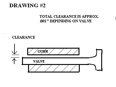
All engine parts wear, and valves and valve guides are no exception. In new condition, valves have a small
clearance fit to the guides. See Drawing #2.
VALVE JOBS
All aspirated internal combustion engines are basically air pumps. The pistons move volumes of air; the valves,
like check valves, regulate which direction the air will travel. Valve design can be a rotary or disc valve, a reed
valve, or a poppet valve. Most cars in the last 40 years, including Porsche, have poppet valves.
Poppet valves are defined as a round disc (with an angle cut on the underside) which is attached to a long stem.
The length of the stem is determined by how the valve fits through the port, and how far the port is from the backside
of the head. The valve head is approximately 30% larger than the port diameter. The port diameter determines the
engine torque characteristics. The exhaust valve head diameter is approximately 70% of the intake valve head
diameter. The valve head lift off the seat is usually less than 25% of the valve head diameter.
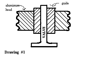
Since a valve reciprocates in motion every two revolutions, some sort of bearing must be used to minimize wear.
With the aluminum heads of the Porsche, a tubular section of brass, bronze, or silicon bronze, called a valve guide,
was pressed into the head. The valve moved up and down in the valve guide. See Drawing #1.
All engine parts wear, and valves and valve guides are no exception. In new condition, valves have a small
clearance fit to the guides. See Drawing #2.
However as the mileage on an engine accumulates, the valves, guides, and seats wear. The valve face and seat
angle are the machined surfaces on the valve and seat ring that come in contact with each other. See Drawing #2.
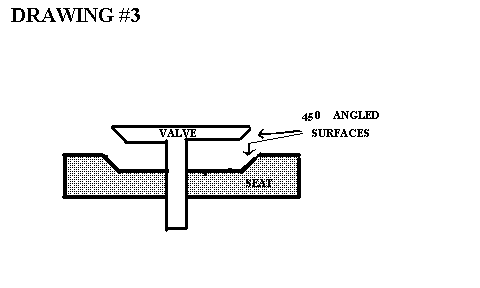
The reason that engines need valve jobs is that there is leakage between the valve face and the seat interface. This is caused primarily
by erosion of the metal of both the seat and valve, and this leakage is compounded by worn valve guides. First the heat paths, that cool
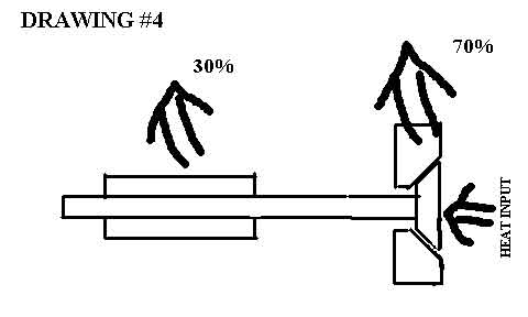
the valve head that has been heated by combustion, go through the valve/seat interface (70%) and the stem/guide interface (30%). See Drawing #3.
As the valve seat erodes, less area is available to pass the heat. As the stem and guide wear, less contact is
available to pass the heat. Therefore both conditions will tend to elevate the temperature of the valve head
and stem, and further increase the wear rate. Second, when the stem to guide clearance increases, the valve
does not seat in the same position when the cam drops it down. Since the valve comes down against the seat
off center, it will hammer the valve and seat interface, to further reduce the carefully machined surfaces, and
thus further elevate the temperatures. See Drawing #4
A valve job can be divided into 4 areas.
1. EXAMINE THE VALVE: remachine or replace
2. EXAMINE THE SEAT: remachine or replace
3. EXAMINE THE GUIDE: remachine or replace
4. EXAMINE THE VALVE SPRING: reshim, or replace and reshim
Section 1 - (Examining the valve)
Clean the valve and ;mike; the stem, (using a micrometer). If anywhere along the length of the valve stem the
diameter is 9.95 or less for the 356 10mm valves; 8.95mm or less (for the intake valves) and 8.93mm or less
(for the exhaust valves) for the 911, 924, 928 2V; 6.95mm or less (for the intake) and 6.92mm or less (for the
exhaust) for the 928 32V, throw the valve away. Note that on the early 356 exhaust valves this is only .0005;
to .001" wear. Now check the taper of the valve stem. This is the difference between the thickest and thinnest
portion. If the taper is .001 or .025mm, throw the valve away. If the valve passes both criteria, check the margin.
The margin is defined as the distance between the edge of the 450 angle surface and the top of the valve. See
Drawing #5
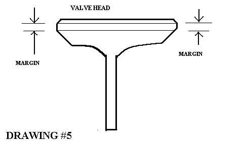
The narrower this distance is, the more likely a thermal hot spot is likely to develop and cause
pre-ignition and/or valve head warpage. See Picture #3.
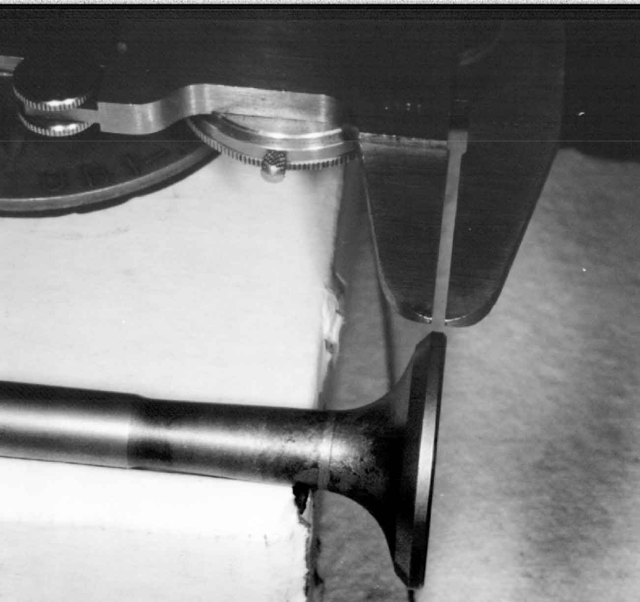
PICTURE #3
The minimum margin on the 356 will vary from 1.7mm (.066) on the early valves to 1.0mm (.039) for the
C and SC intakes, and 2.05mm (.079) for the C and SC exhausts. For the other models a good rule of thumb
is to use a standard of 1mm (.039) on all other valves. See Drawing #5A.
If the valve passes the third criterion, the valve face can be machined with a 450 angle, provided that after
machining, the margin is equal to, or greater than, the minimum.
NOTE: Considering on how small the tolerances are and how much labor is required to get to this point, it is
frequently wiser to just replace all the valves.
Section 2 - Examining the seat.
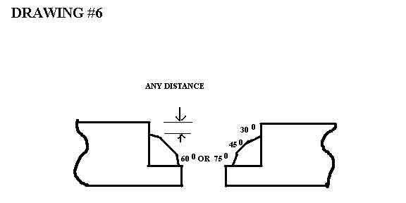
Clean the seats and examine them. If the seat is loose in the head, replace the seat. Replacement oversize seats
are sometimes not available. Check with your supplier. If the top 300 angle is below the top surface of seat, replace
the seat. See Drawing #6.
Also for the 911, 944, and 928 the valve seat wear limit is measured by the protrusion of the valve stem above
the spring seat surface. The valve seat wear for the 924 is also determined by the depth of the top edge of the 450
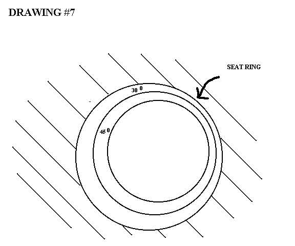
angle to the head surface. If the valve seat has been originally cut off center, or had heavy erosion, then re-cutting
the seat on a true center will be the only way to see if the seat is usable. Cutting the seat will be discussed later.
See Drawing #7
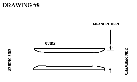
Section 3 - Examining the guides
Clean the guides on the outside and clean the insides with a guide brush. Measure the inside diameter of the
guide with a small dial bore gage, or a hole transfer gage. The guides will bellmouth at the chamber side, so
measure there. See Drawing #8.
The guide will typically oval out in the direction of the rocker actuation for those engines with rocker arms.
See Drawing #9.
Measure the diameter at the tip of the guide. The wear limit is
10.07mm for the 356. For the 911 the wear limit is 9.10mm for the intakes and 9.13mm for the exhausts. For the
944 the wear limit is 9.05mm. The 924 has a wear limit of 9.10mm for the intake and 9.13mm for the exhaust. For
the 928 with the 9mm valves, the wear limit is 9.05mm; and for the 7mm valves the wear limit is 7.05mm. An
alternate way to determine the wear limits of the guide is specified for the 944 and 928 by measuring the lateral
valve head rock with the valve head a certain distance off the valve seat. If the guide diameter is equal to the
wear limit or greater, replace the guide. If the guide bore is less than the wear limit, but ovalled out more than
.001" or .025mm replace it, because to find a true center of an oval hole with a valve seat cutter pilot is impossible.
Removing and installing guides will be discussed later.
Section 4 - Examining the valve springs.
Clean the valve springs. If there is any rust pitting on the coils replace all of them. If the valve are the old double
spring variety for the 356 replace them. If the springs are cocked over while sitting on a flat surface, replace them.
Measure the spring tension and determine the variance in pressure. Used springs should be within +/-5%. New
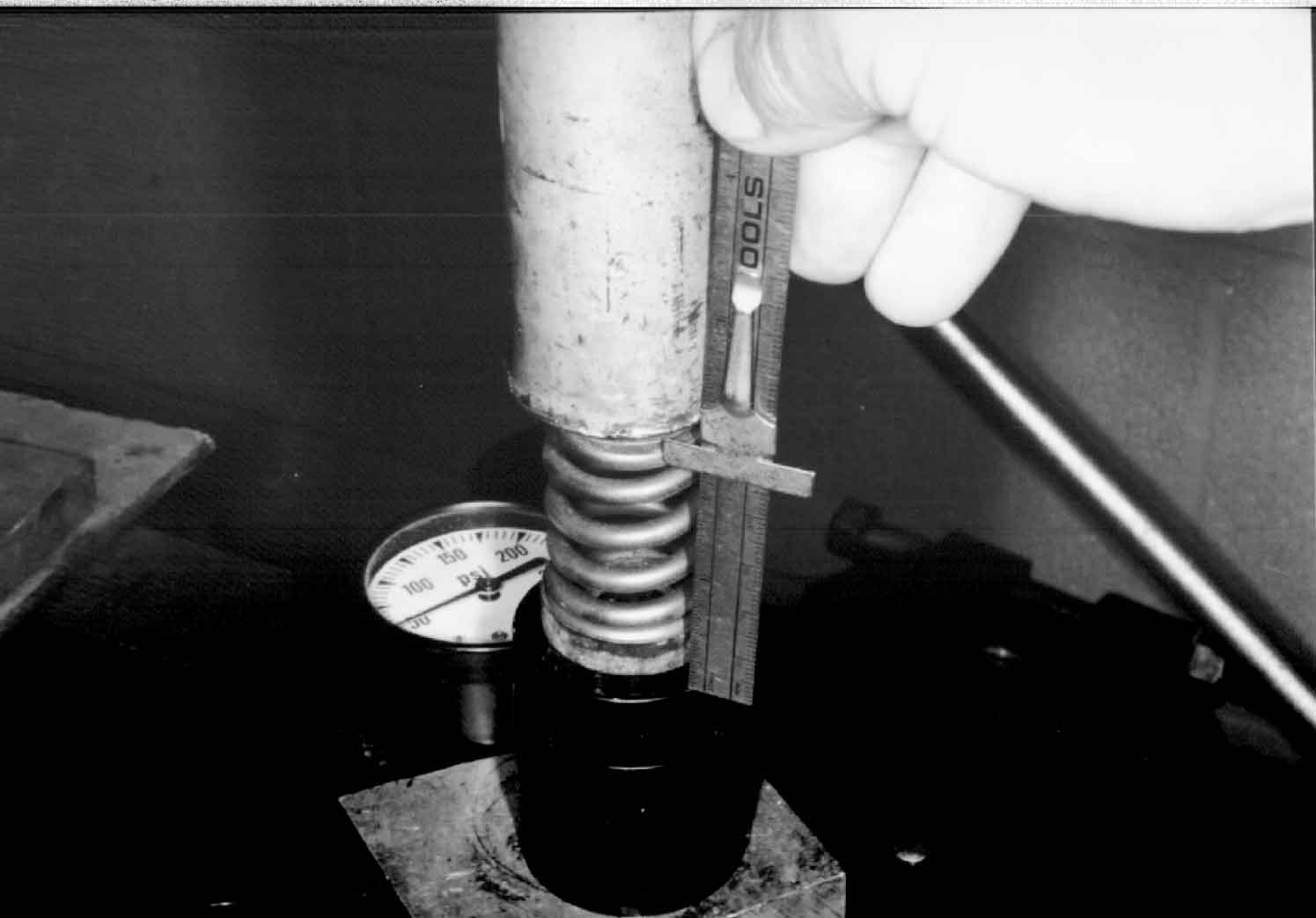
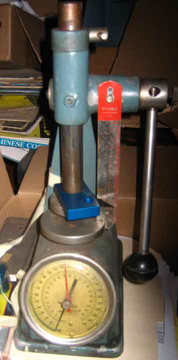
springs will be within 2%. For blueprinting, add shims to set spring tension at maximum at test height. Measuring
valve springs can be performed on a Rimac valve spring tester where the spring pressure can be read while
compressing the spring to a specified height. This tester costs about $500.00. A more economical tool is made
by Goodson Machine Co.; it is about $150.00. This is a hydraulic load cell connected to a Bourden gauge. The
gauge is calibrated in 5 lb increments to 300 lbs. Testing a valve spring is performed by putting a valve spring
on top of the tester and installing the pair into a press. Actuate the press until the arbor presses the spring to a
specified test height. Read the gauge to obtain the spring pressure. See Picture #4 Much care must be exercised
when using this tool in that it has a lot of hysterisis. Values should be read while squeezing the tool, not while relaxing
the tool. For non street applications use a Rimac tool.
For the 996 the pressures were 60 lbs closed and 160 open.
The spring heights were:
RIMAC TESTER
Changing the guides can be a big problem. Guides can only be ermoved safely by pressing them out. The
first operation for 9mm and 10mm valve guides is to drill them with a 27/64 drill bit and then to tap the
guides with a 7/16 X 14 tap. Install a stepped drift against the valve guide through the chamber side and
install a 7/16 X 14 bolt into the valve guide from the cover side until it contacts the drift. See Drawing #10
and Picture #5.
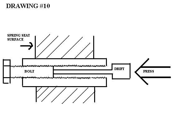
For the 7mm and 8mm guides use a 11/32 drill and a 3/8 X 16 tap. The bolt will be a 3/8 X 16 thread size.
Using a press, apply pressure against the drift, pushing the guide with the bolt in it outward to the valve cover
area.
For the 356, set the bed of the press against the valve cover surface for the intake guides. For the exhaust guides
make a fixture with approximately a 30 angle for a bed fixture to press out the exhaust guides in a vertical
direction. See Drawing #11.
I have since used for the 356 a tube described below.
For 911 use a tube of approximately 1 1/4"; on the outside with a length of 6"; and install it on the valve spring
side of the head. With the tube sitting on the bead of the press, press out the guide. For the 944 and 928 2V place
the head cambox side down on some wood on the bed of the press and press out the guides. For the 928 4V use
the setup recommended in the factory manual by making an angled wood base to press against.
Next after removal,;mike; out the guide boss hole. Usually an ovality will be noticed in the hole. The guide boss
hole must be reamed just enough so that the hole is straight and round. Carefully use and adjustable reamer, and then
measure the hole again. For the 356 the hole will usually be bigger than 14.02mm, which is the maximum size for
the standard size guide. Add .04mm to the diameter of the hole and see whether the the first or second oversize will
fit. Then lathe the outside of the new guide for a .04mm press fit. If a factory guide is used, keep the press fit to
.025mm as this type of guide is very soft and difficult to press. For the 911 the guide boss hole will usually be
bigger than 13.08mm after it is reamed. Use .05mm for a press fit and choose the appropriate guide or lathe an
oversize guide to fit. For the 924 the hole is about 14.00mm for the standard fit for a new head. For the 944 and
928 2V the hole is about 13.00mm with a required press fit of .06 to .08mm. After reaming, lathe the first oversize (13.27MM)
To fit with an appropriate press fit. For the 928 4v the standard bore is 11.00mm with a press fit of
.06 to .08mm. The first oversize valve guide is 11.26mm lathe to fit.
If the guide is not a factory guide, find the best quality (usually most expensive) guide to fit. The factory style guide
has the best concentricity, which will ensure that the valve will seat exactly in the center of the seat. The cheap valve guides
have very poor concentricity and consequently have a large probability in ruining the valve seats because the valve is seated off center.
Recapitulating the valve guide section, it is safest to get the first oversize factory type valve guide. Then lathe the
outside diameter for the correct press fit. In some cases, if the head has had many valve jobs performed on it, or has
had cheap guides previously installed, the trued guide boss hole will require will require a second oversize valve
guide. Check for availability of these valve guides. The factory oversizes are expensive and sometimes not available.
Aftermarket valve guides are usually not available in oversizes. In some cases, custom valve guides must be made
to fit the boss hole. When installing guides, be sure to heat the head to 275 F and press in the guides. After the
guide is installed, be sure to ream and hone the guide to 10.00mm (9.00mm, 8.00mm, or 7.00mm depending on application)
to ensure that it is not too small on the ID which would cause valve seizure.
Lately the aftermarket guides have become swo hard thet my carbide reamers won't cut them. So I am using my local machine shop who uses a Sunnen guide honing setup.
Cutting the seats is performed with new or next-to-new guides for reasons stated earlier. Tapered pilots are the
most accurate seat cutting pilots to use. See Picture #6. The upper three pilots depicted are tapered pilots 8.98mm, 9.00mm,
and 9.02mm. The lower pilot is an expandable pilot-less accurate.
PICTURE #6
The 45 angle cut is the first machine operation to perform. Cut enough of the 45 angle to make a complete angular circle. See Drawing #12.
The lightly cut the 60 or 75 angle to the bottom and a 300 angle to the top. See Pictures #7 (45 angle cut into
the dye), #8 (30 angle cut into the dye), and #9 (60 angle cut into the dye). Since there are three intersecting
concentric cones, at angled surfaces, we have defined a truncated cone on the 45 angle that has the same width
all the way around the cone. Measure the width of the 45 surface. See Drawing #13.
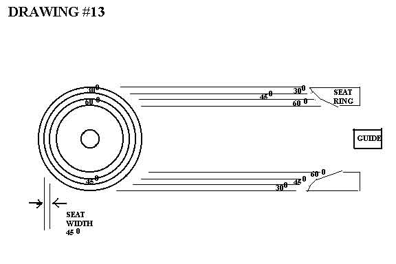
For the 356 we want 1.1mm for the intake and 1.4mm for the exhaust. Summarizing the other models:
| MODEL | SEAT ANGLES | SEAT WIDTHS |
| 911 2.0 | 30, 45, 75 | 1.1mm In 1.45 ex |
| 911 2.2,2.4 | same | 1.4 both |
| 911 3.0 | same | 1.2 in, 1.4 ex |
| 911 3.2 | same | 1.2mm in, 1.4 ex |
| 944 | 30, 45, 60 | 1.5 in, 1.8 ex |
| 928 | same | same |
| 924 | 30.45,60 in
15,45,60 ex |
2.0mm in, 2.4 ex |
| 996 | 15.45.60 | 1.1mm IN 1.4mm EX |
(Be careful with the 996 as ther is not much seat material to work with.)
After setting the seat widths, wipe some Prussian red or blue on the 45 angle and drop a valve in the guide and
turn it lightly. When the valve is removed a dye patch will be visible on the valve face defining the point of contact.
See Picture #10. We want this line to be about .5mm from the top of the edge of the 45 angle. See Drawing #14.
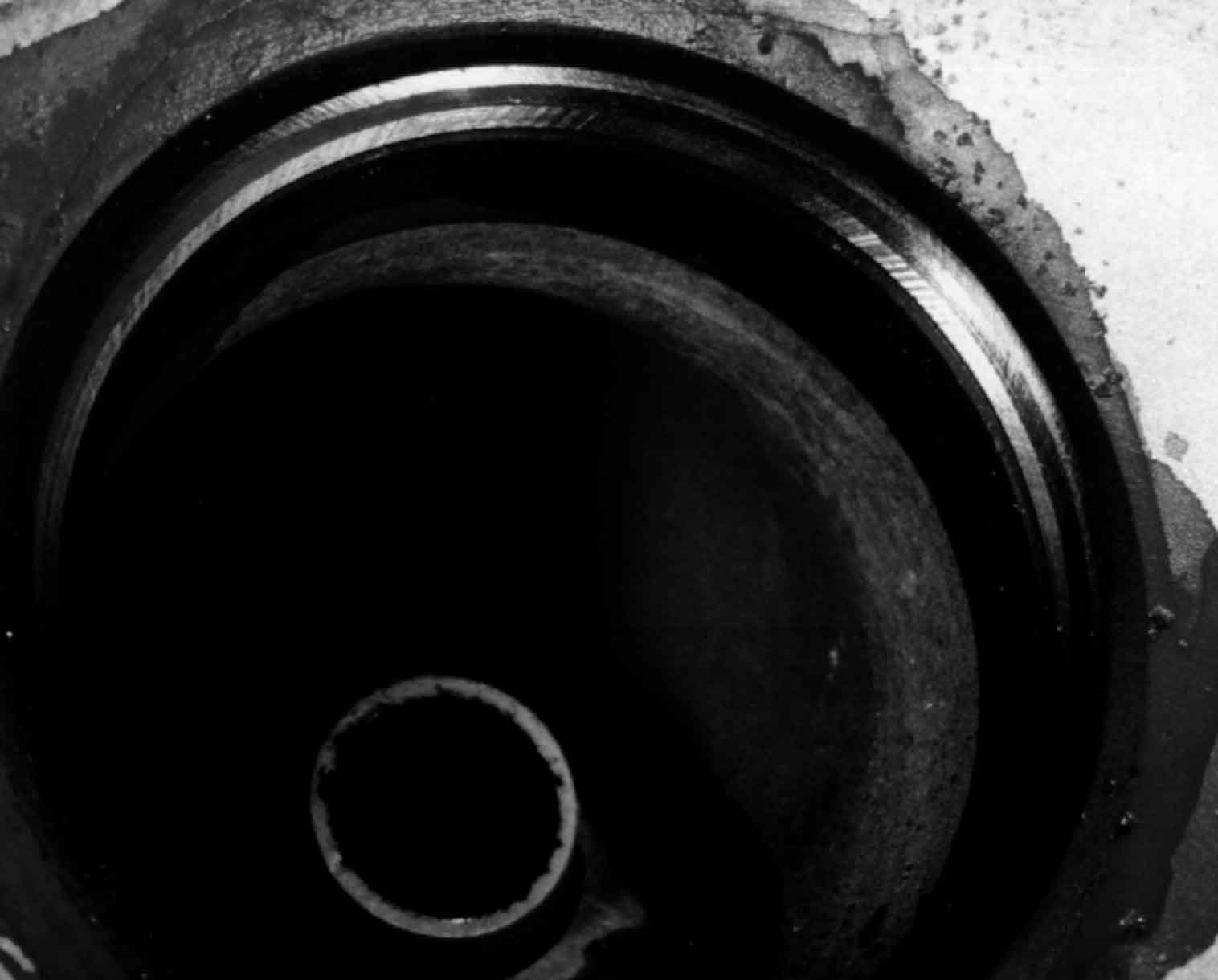
PICTURE #10
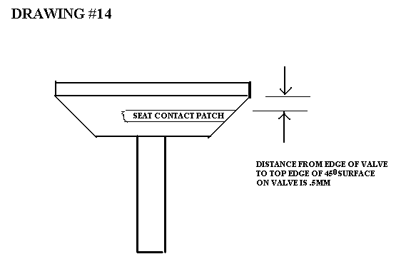
To raise this line , cut more on the 45 and the 60 ( or 75). To lower this line, cut more on the 45 and on the 30 angle. Recheck with the dye. After setting the correct height on the face and the width of the seat, lap in the valve.
To finish the valve job, shim for the correct spring heights ( using the factory tool to make it easy), install valve seals where applicable, and install springs.
The correctly done valve job will last as long , or longer than the factory valve job. A tight valve job will add to the crispness of the engine, and to the enjoyment of the car's performance.