TORSION BAR BUSHING REPLACEMENT
Even though this topic has been discussed a lot in the past, a review might be beneficial for the new owners of these older cars (1989 and earlier). The following article presents the replacement of the front torsion bar bushings in a 1978 911 SC.
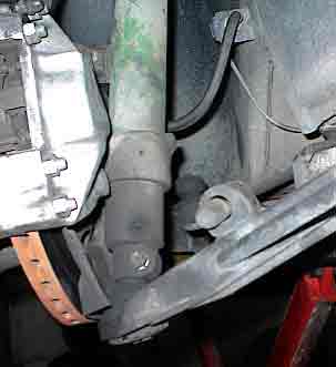
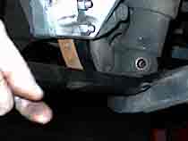
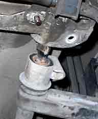
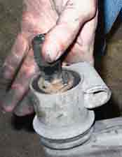
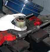
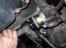
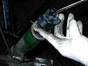
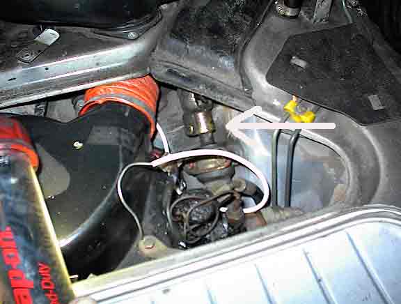
Picture No. 003WEB shows the original right front torsion bar bushing in place.
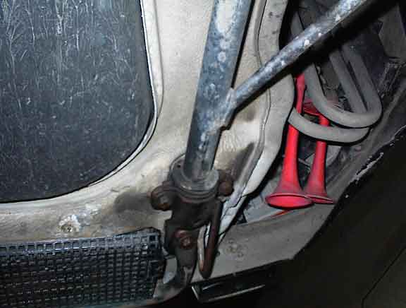
Pict 003
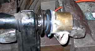
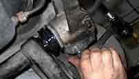
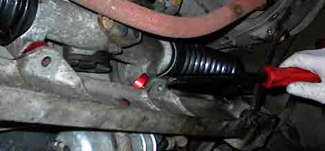
Picture 006CROPWEB shows the rear bushing of the left trailing arm assembly. Note that the rack cover partially obscures the original rear bushing.
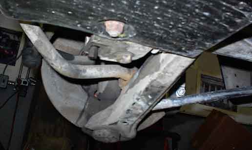
Pict 006
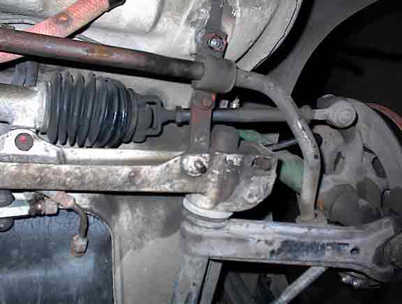
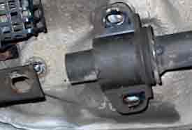
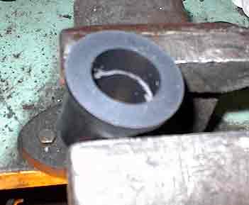
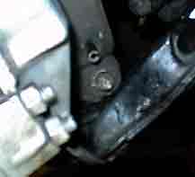
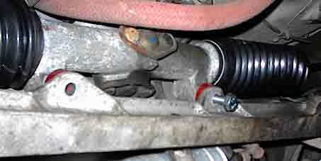
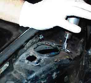
Picture No. 010WEB shows the right rear torsion bar bushing area with the rack cover removed.
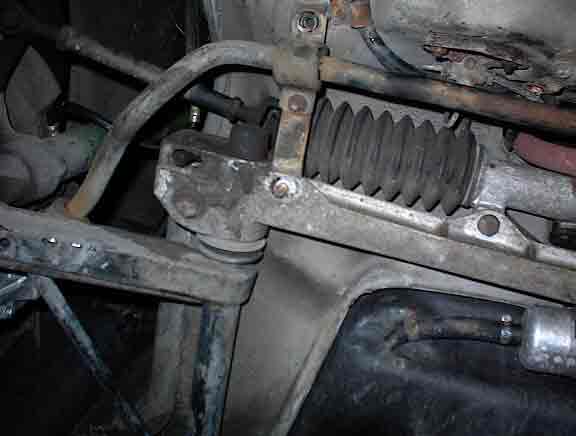
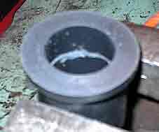
Picture No. 012 shows the left rear torsion bar area of the left trailing arm.
To remove the torsion bar bushings, the trailing arms have to be removed from the car. To remove the trailing arms, the trailing arm ball joints have to be disconnected from the struts .
There are two ways to accomplish this task:
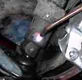
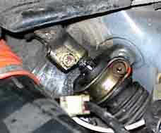
The first technique (the easier way) is to knockout the roll pin that retains the ball joint pin inside the strut. (See Picture No 015Cropweb.)
Pict 015
The second technique is to unscrew the ring nut that attaches the ball joint to the arm.
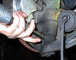
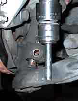
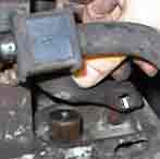
Picture No. 016cropweb shows a punch (or drift) on top of the partially removed nut on the ball joint retainer pin.
Pict 016
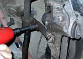
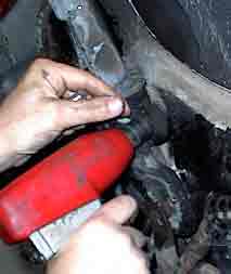
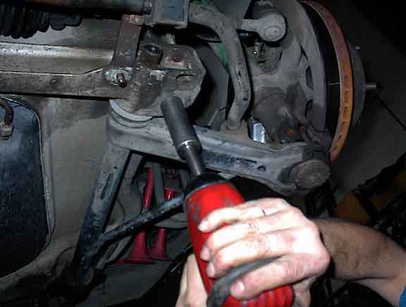
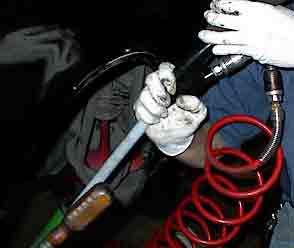
The nut is left here so as not to injure the threads on the pin. As long as the pin is not seized, the pin will come out with a light blow. Picture No. 017cropweb shows a partially seized pin being massaged out of its hole by an air hammer.
Pict 017
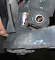
This is a particularly delicate procedure and much care has to be exercised in not damaging the threads. Picture No. 019cropweb shows that pin starting to come out of its hole.
Pict 019
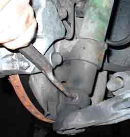
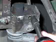
Picture No. 024cropweb shows a method of levering out the ball joint pin out of the bottom of the strut with a pry bar.
Pict 024
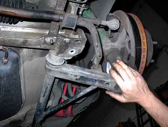
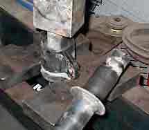
Picture No. 026cropweb shows a slightly different method in the removing the ball joint pin out of the housing. An air hammer is used to apply a vibrating force to the flange of the trailing arm to remove the pin out of strut socket.
Pict 026
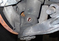
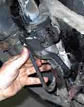
Picture No. 027cropweb shows the final removal.
|
Pict 027
In order to finally remove the trailing arm from the car, the sway bar has to be disconnected from each of the trailing arm mounts. Picture No. 020cropweb shows the rear sway bar bushing mounts being removed from the body.
Pict 020
Picture No. 021 and No .022 and No. 023 shows the front torsion bar brackets being removed from the body.
Pix 021
Pix 022
Pix 023
Picture No.028cropweb shows the long adjusting bolt being removed from the torsion bar rocker adjuster.
Pix 028
After the bolt is removed, the rocker can be slid off of the end of the torsion bar (as shown in Picture No. 029cropweb)
Pix 029
Next remove the rack beam attachment bolt. (See picture No. 031).
Pict 031
This bolt goes through the retaining mount of the trailing arm. It must be removed in order to slide the trailing arm forward and out of the car.(See Picture No. 032 and 033).
Pix 032
Pix 033
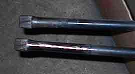
With some higher mileage cars, the rear bushing wears so much that the torsion bar rubs the edge of retaining collar of the arm. It will usually produce a notch in the torsion bar (a stress riser). In the extreme, the torsion bar will break at this point . (See picture No. 035and No. 036cropweb).
Pix 035
Pix 036
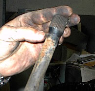
Wiggle and pull the torsion bar out of the trailing arm.
It is very important to eliminate the sharp edges (stress risers) and all corrosion. All the wear spots and corrosion must be polished. See Picture No. 047cropweb.
Pix 047
Removal of the bushings was not too difficult in this particular case. The front bushings were removed by pressing off the metal collars as shown in Picture No. 039.
Pix 039
The wings of the front collars were positioned on the press plates to allow clearance for the trailing arm to fall through the press plates. The rear bushing collar was placed in a bearing press plate fixture and the trailing arm was pressed through the collar as shown in Picture No. 040cropweb.
Pix 040
The remaining rubber was removed fairly easily. Neatrix (TM) bushings were selected with ride comfort considerations as a concern. (But they still squeak.) Because the installed bushings are in such a remote location, they cannot be drilled for external lubrication holes. Instead, grooves were cut into the inside surface to hold lubricant for a longer period of time. See Picture No. 056 and 57.
Pix 056
Pix 057
The new bushings were first pressed into the front and rear collars. (2 front and 2 rear ). The rear collars (and installed bushings) were pressed on the trailing arms using a vice as shown in Picture No. 058. When the collar bottomed out on the trailing arm, the arm was repositioned as shown in Picture No. 058.
Pix 058
The front collars (with installed bushings) were positioned by hand pressure. The assembled arms were fitted back into the rack beam . See Picture No. 062cropweb.
Pix 062
The rack beam mounting bolts were installed through the arms into the body (one side is assembled at a time). See Picture No. 063. The front brackets were reinstalled. The ball joint pins were reinstalled into their strut housings.
Pix 063
With this particular car, the Bilstein struts were also replaced. The Bilstein strut inserts are retained at the bottom of their housings by a roll pin (which is above the ball joint retaining pin.) See Picture No. 066.
Pix 066
When the roll pin is removed, the strut insert should simply pull out of the housing. However one strut was rusted into the housing. Heat had to be applied to the pin hole to free up the rusted strut shaft. See Picture No. 069.
Pix 069
After the strut inserts are removed, be sure to remove the rubber snubbers that will get stuck in the bottom of the housings. See Picture No.064.
Pix 064
This strut housing had to be vacuumed out to clean the rubber particles (disintegrated snubber) that sat in the bottom. See Picture No. 065.
Pix 065
This car was to be lowered and a rack spacer kit was being installed. (Picture No. 048).
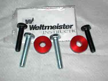
Pix 048
The bushings should be inserted between the rack and the rack beam. See Picture No. 052.
Pix 052
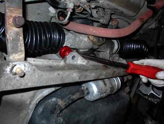
I n order to accomplish this smoothly and to prevent the steering column from binding, the pinch bolts in the first universal joint in the steering column have to be loosened. And then the mount holding the snout of the rack has to be loosened (2 allen bolts). See Picture No. 050.
Pix 050
Apply the bushings by gently prying the rack upward. See Pictures No. 053 and 054. Note in Picture No. 055 how the rack has shifted upward.
Pix 053
|Pix 054
Pix 055
Also since the car was to be lowered, the outside of the strut bearing mounting holes were clearanced an additional 3mm. See Picture No. 068.
Pix 068
This is to allow more alignment compensation for excessive negative camber which accompanies large amounts of suspension drop.
In summary this is a task which can be performed in most garages; however having a press and large vice speeds up the operation. There are other techniques which can be used instead of a press but the operation time is considerably longer. Additionally if there are any other unusual problems such as frozen strut inserts or frozen ball joint pins etc, having additional equipment is a plus.