356 ELECTRIC FUEL PUMP INSTALLATION
356 Electric Fuel Pump
By Mat De Maria
The 356 model Porsche was manufactured from approximately 1950 to 1964. After many years of use, some parts of an individual car would wear out, with the result that many of the functions that a car is supposed to do would degrade in quality. One of the most annoying problems with these high mileage (or unrestored) cars is the difficulty in starting the engine. The solution is generally two-fold:
The first part of the solution is to clean all the battery terminals and grounds of the 6 volt system. This includes on the 356 Bs and Cs, reconfiguring the battery ground. As delivered by the factory, the battery ground is connected to the bolt at the base of the hold-down bracket. When the cars become rusty, this ground is tenuous at best. It is far more effective to weld a nut or stud to a solid part of the body and to connect the ground cable to this. In addition to this fix, as a matter of protocol, install new distributor points.
The second part of the solution is to enable the fuel to reach the carburetors quicker in order for the accelerator pumps to work sooner. On an old car, the fuel pump is usually worn and is not working as efficiently as a new pump. The worn fuel pump is usually taxed with the job of drawing fuel through a partially clogged gas tank petcock and/or through a partially clogged tunnel fuel line. The quick interim solution is to install an electric fuel pump. This is in lieu of immediate renovation and/or replacement of the petcock, fuel line, or stock fuel pump. This is also added insurance for a restored car to ensure its reliability, especially when it is not driven for long periods.
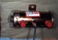
The best choice for a 6 volt vehicle is the Bendix fuel pump. See Picture #1.
PICTURE #1
This pump has a good reputation, well known for its reliability for at least 35 years, and it is even still available through any NAPA outlet.
The best location for the installation of this pump is in the passenger side floorboard area. See Picture #2 where the mounting area is marked with masking tape.
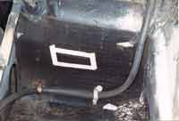
PICTURE #2
This area is chosen because it is near the fuel line in the tunnel and it is a protected area from rain or dirt. It is normally mounted on the vertical bulkhead wall. Remember it has to clear the floorboard that rests above it. For those cars (such as the one in the illustration) with the tar sound deadener paper still on the wall, cut a rectangle from the wall the size of the base of the fuel pump. A sharp chisel is used here to cut through the paper with just hand pressure. Place pump against the wall in the chosen spot that has had the tarpaper removed and mark the centers of the mounting flange holes of the pump with a punch. See Picture #3 where the sound deadener has been cut out and the pilot holes have been drilled.
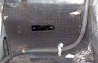
PICTURE #3
Next two 'Nutserts' are used to mount the pump to the wall. This is a new product marketed by the Wurth company. It is similar in function to a rivet that has threaded barrel attached to it. Drill the appropriate size clearance hole for the 'Nutsert'. Crimp the 'Nutsert' into the hole. See Picture #4 for a view of an uninstalled 'Nutsert' shown in the hand, an installed 'Nutsert' in the right hand hole, and the installation tool on the floor.
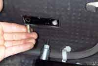
PICTURE #4
In this application a 'Nutsert' for a 6mm thread size was chosen. Since the pump carries its ground through the case and mounting flange, care must be exercised to ensure that the ground will not be affected by long term corrosion. A chisel-pointed lockwasher is placed between the pump flange and a ring connector. Both are underneath a 6mm mounting bolt. See Picture #5 for a view of the chisel-point lockwasher mounted on the attaching bolt.
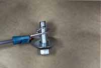
PICTURE #5
The ring connector is crimped onto a ground wire. This ground wire will be fastened by a spade connector to the right hand bulkhead brace by using a special grounding rivet. (This is also available through the Wurth company.) See Picture #6 for a closeup picture of the grounding rivet with its tines that dig into the sheet metal brace.
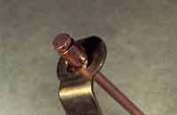
PICTURE #6
The power supply wire connects to the pump power wire by means of a standard blue butt connector. This in turn is connected to a Bakelite fuse holder that holds an original style ceramic fuse. The other side of the fuse holder will lead to a Porsche bullet connector wired to terminal 15 at the ignition switch. In this particular application, sheathing was installed onto both the power and ground wires from the pump for a short distance, and an Adele clamp fastened this pair to the bulkhead wall by an 1/8" rivet.
See Picture #7 to see how this was done. The power line is then led through a gronimeted hole in the upper part of the bulkhead brace.
PICTURE #7
See Picture #8 for a look at the grornmeted hole for the power supply wire to the pump.
PICTURE #8
The next phase of the installation is to connect the fuel lines. The fuel lines have to be aimed at the hole in the tunnel bracing in order to minimize bending and kinking the hose. A right angle brass piece (1/8" pipe thread) is used in conjunction with a 1/8" male pipe thread with a 5/16" tube end. In order to create a better seal at the pipe thread interface, Teflon tape is applied to the threads. Holding the pipe threaded fixture in our hands with the threads facing us, the Teflon tape is wound around the threaded end for 1 revolutions in a clockwise direction. This is done 2 threads below the end of the threads. The purpose of this is to prevent the tape from peeling off backwards from the threads while tightening it into the female threads; and also if any tape is overhanging the threads it will possibly break off and clog something downstream. See Picture #9 for a look at the brass pieces and tape.
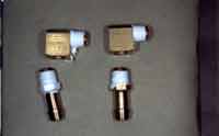
PICTURE #9
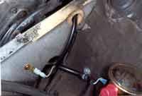
On the 356Bs and Cs, the metal fuel line coming through the bulkhead wall is connected to the tunnel line by a short section of braided rubber hose. See Picture #10 for a view of this hose (with the pointer on it).
PICTURE #10
This hose is removed. The upper tube here is already slightly flared but the lower one is not. Carefully using a brake tubing flare kit, slightly flare the tunnel tube. This is done in order to keep the installed rubber hose from slipping off a straight section of tube if the clamp or rubber hose loosens up with age. The old style fabric hose is used because the fuel pressure is low and because this hose will make shorter radius turns than the stiffer fuel injection hose. This hose is attached with crimped ring clamps because this is a more permanent mode of attachment than worm gear clamps. See Picture #11 for a view of the hose and the crimp clamps.
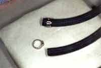
PICTURE #11
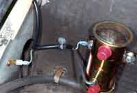
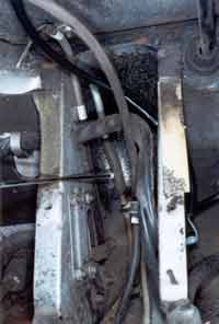
Also see Picture #12 where the lines are connected onto the fuel pump and led through a grometed opening in the brace.
PICTURE #12
On the 356As it is easier to connect the fuel petcock, underneath the dash to the input of the fuel pump. The output of the pump can either be connected to the metal line adjacent to the petcock or to the metal line that has been cut back about two feet and slightly flared inside the tunnel.
In summary, this modification is an efficient interim repair for an old unrestored car, and it is a very helpful addition for a restored car. Even though a ticking sound will be audible from the new fuel pump, it will be offset by the increased reliability in starting and driving.
At the time of this update 9/06 AC Delco still makes a very nice reliable 6v pump P/N EP11 (OR GM P/N 6414670)
NAPA sells a 6v pump under their P/N P4259 or under their non-Napa number P/N E8011. (Airtex, Carter, or Federal Mogul)
Performance Products still sells a 6v pump which visually looks like the carter (NAPA).
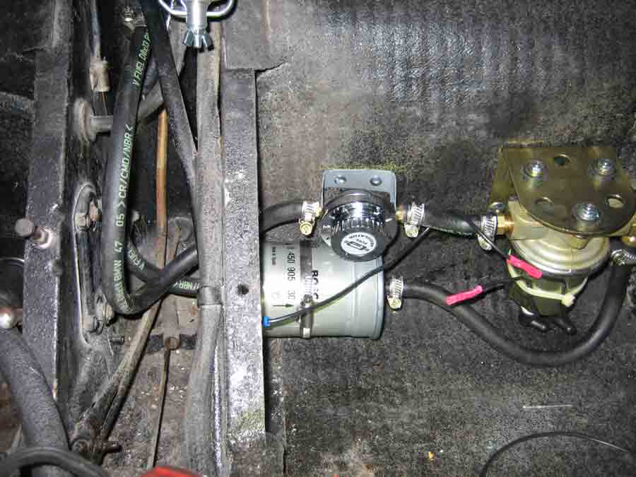
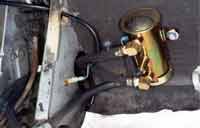
This is a picture of the Airtex (Napa) pump installed with a pressure regulator to reduce the 5 psi pressure to a lower amount for the 32 pbic's